Generator Design
Even when you know your way about the Virtual Developer API, its open source components to ease generator development and the Virtual Developer IDE to code, run and debug your generator, there is still one big issue that we did not yet talk about.
What's the best practice to follow when you want to come up with a new generator?
The following sections give the answer.
Design Process
| Step | Result | Task |
|---|---|---|
| 1. | Reference Implementation | Develop a reference implementation for the type of software that you want your generator to generate source code for. The reference implementation is the source for design patterns and the software architecture. |
| 2. | Files, Key Elements | From the reference implementation identify files and key elements within those files that your generator has to create. |
| 3. | Metamodel | From the files and key elements derive a metamodel that is then used for the creation of object instances that represent such files and key elements. |
| 4. | Modeling Language | If you do not yet have a modeling language that is ready to use, design a new one. This is a not so easy task. It may be worth to have a closer look at the Virtual Developer Modeler that already ships with some modeling languages. |
| 5. | Test Model | Create some test models. |
| 6. | Metamodel Mapping | Map the language concepts of the modeling language to files and key elements that you have identified in 2. The ideal way to do this is to not have a look at keywords in the modeling language but at the metamodel that is the basis for the results of the model access (the very first transformation step of each generator). |
| 7. | Transformation Step Tree | Define a transformation step tree that is capable of implementing the mapping that you just created in 5. |
| 8. | Generator | Develop a new version of your generator. |
| 9. | Issues and Requirements | Run and debug your generator by using the test models that you have created in 5. |
Steps 4. to 9. might have to be executed repeatedly.
Modeling Tool agnostic Transformation Steps
The shortest possible transformation step tree has exactly three steps: Model Access, Model Converter, Generation Group.
(Access) >>> (Converter) >>> (Generation)
The drawback of this basic approach is that the model conversion depends on the modeling tool that is being used to create the input for the generator. To become more flexible, you can add one extra step: one more model converter. The PersistenceToJPAConverter is an example taken from the gApp JPA Generator that generates Java code.
(Access 1) >>> (Converter 1) >>> (PersistenceToJPAConverter) >>> (Java Generation)
The Converter 1 creates an output model that is independent of the employed modeling tool. By replacing the Access 1 and the Converter 1 with Access 2 and Converter 2 you can use a different modeling tool for the same generator output.
(Access 2) >>> (Converter 2) >>> (PersistenceToJPAConverter) >>> (Java Generation)
The output of Converter 2 is the same as the output of Converter 1.
Metamodel Mapping in a Model Converter
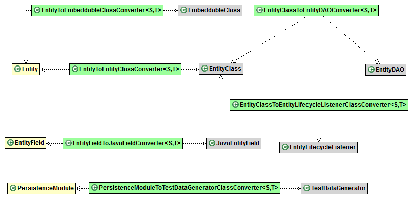
We start with an example of a model converter step and show some of its metamodel mapping. In the following class diagram you see some classes that are used within the PersistenceToJPAConverter model converter. Metamodel classes that are used for the input of PersistenceToJPAConverter have a yellow background. Metamodel classes that are used for the output of PersistenceToJPAConverter have a gray background. Element converter classes that are used within PersistenceToJPAConverter have a green background.
Note
This example includes element converters that take an element as input that has been created within the same model converter. This is not an exception or a hack but a best practices in certain situations.

For your own generator you sketch such a map for a model converter step by listing the metatypes of the input elements on the left and the metatypes of the output elements on the right. Then you draw arrows from the left to the right and from elements on the right to other elements on the right (not to be confused with the arrows in the above class diagram, which mean dependencies). You use this sketch to create the element converter classes for the model converter step. You need an element converter for each of the drawn arrows.