Wiring
Raspberry Pi wiring
As a good reference for the GPIO pins on the Raspberry Pi you can hava a look at https://pinout.xyz.
Step-by-step guide
-
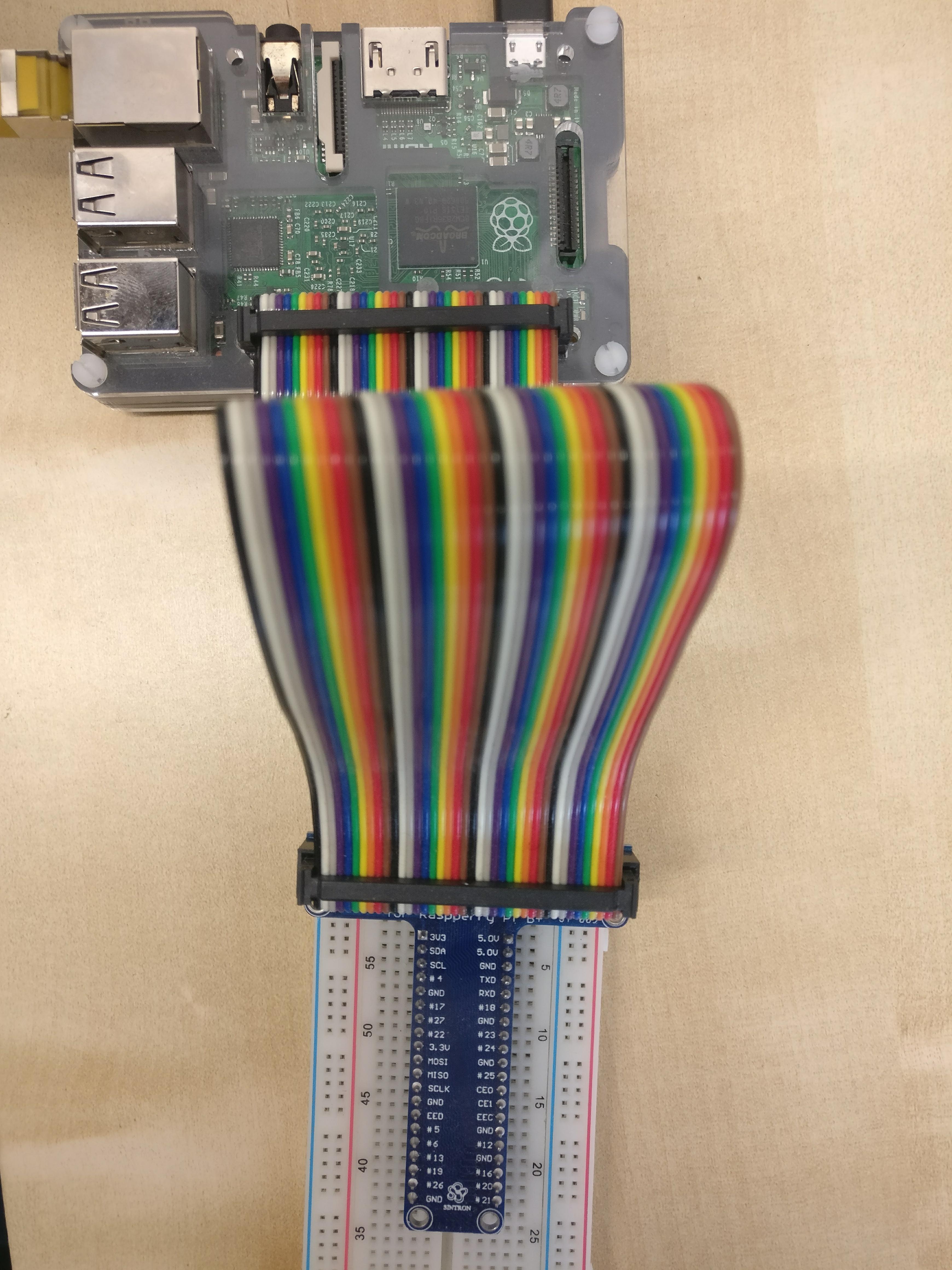
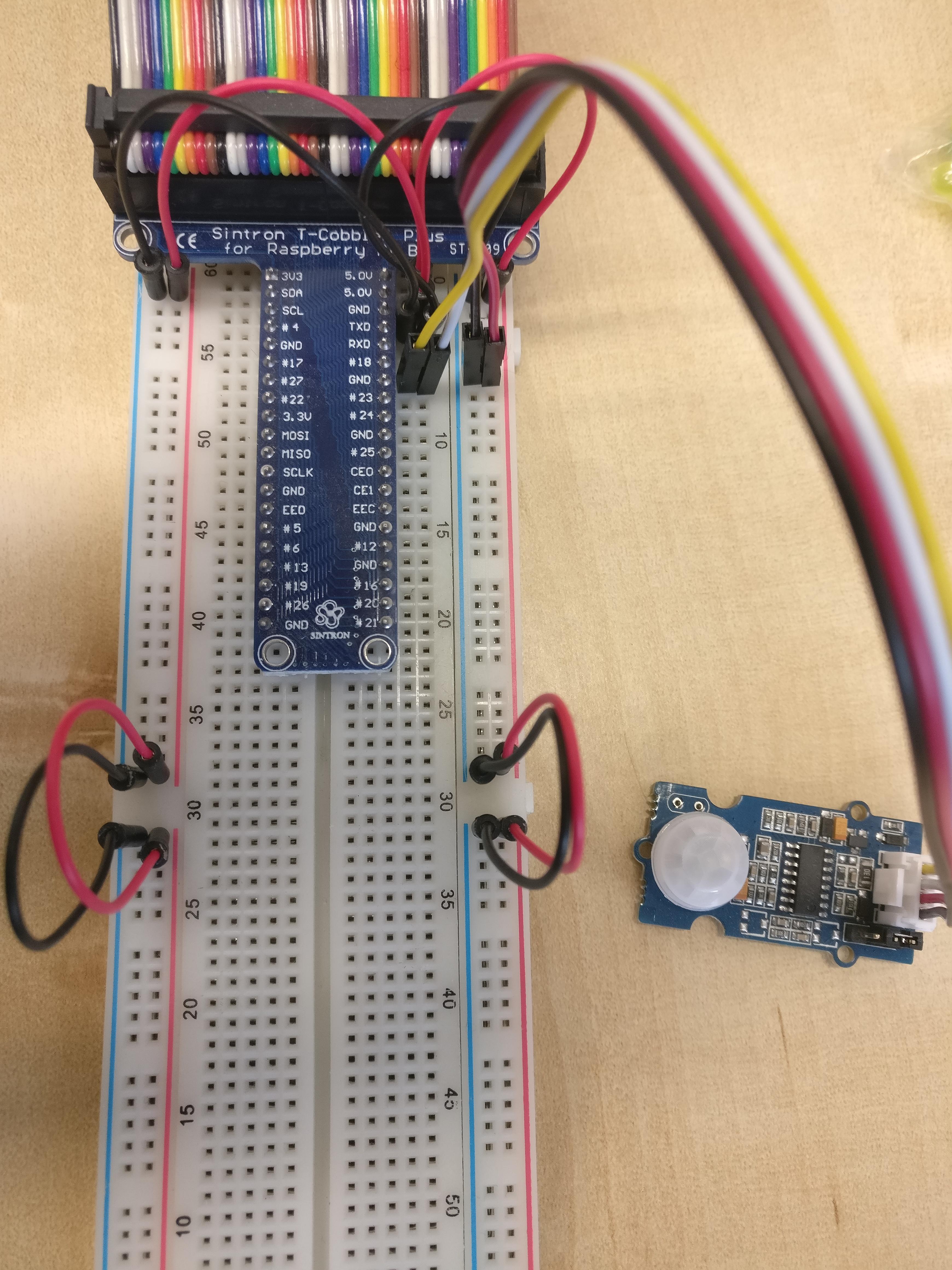
Connect the Breadboard with the Raspberry Pi.
-
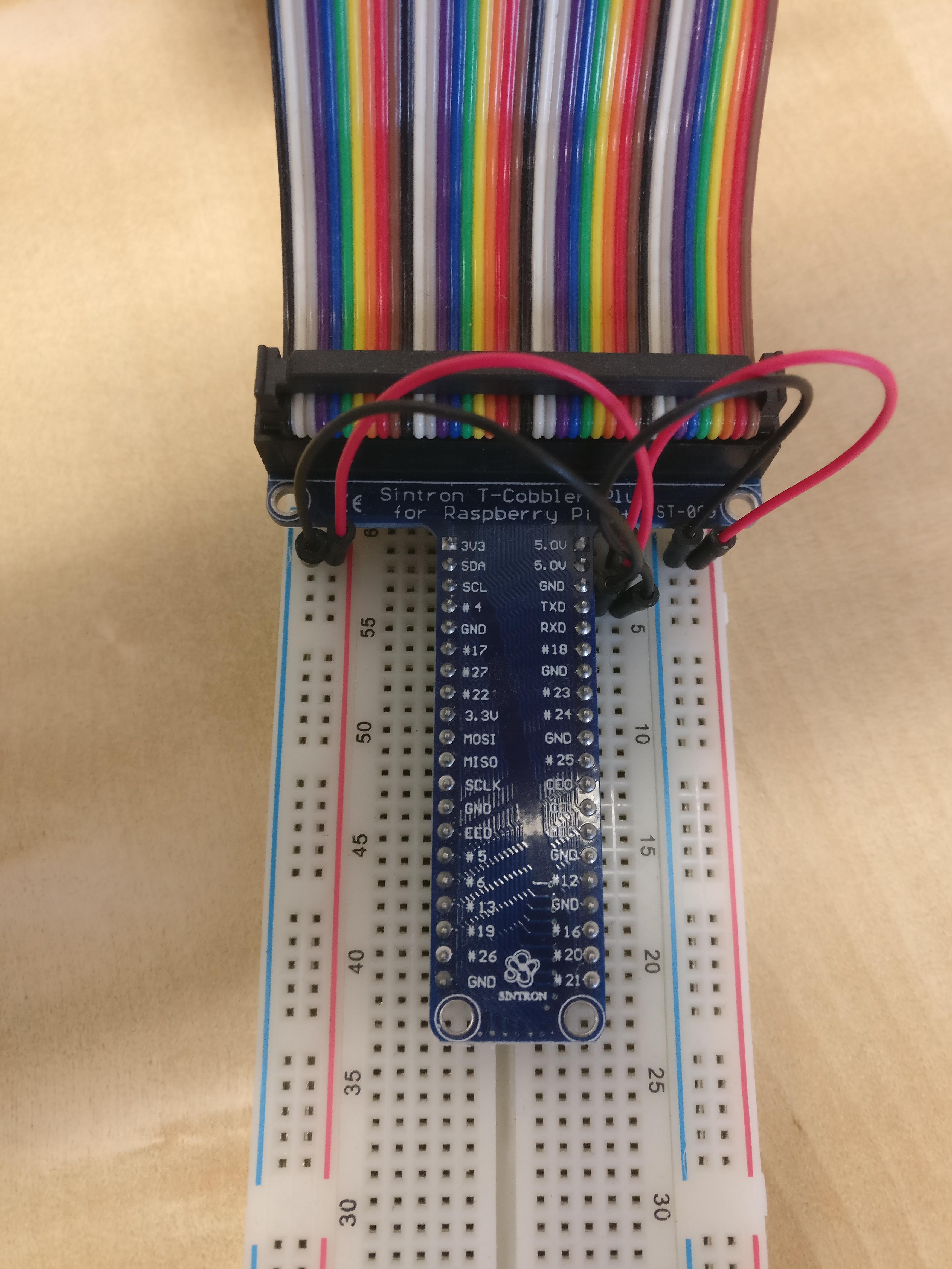
Connect the voltage (5.0V) with the voltage (+ / red) on both sides of the Breadboard and connect ground (GND) with ground (- / blue) on both sides of the Breadboard.
-
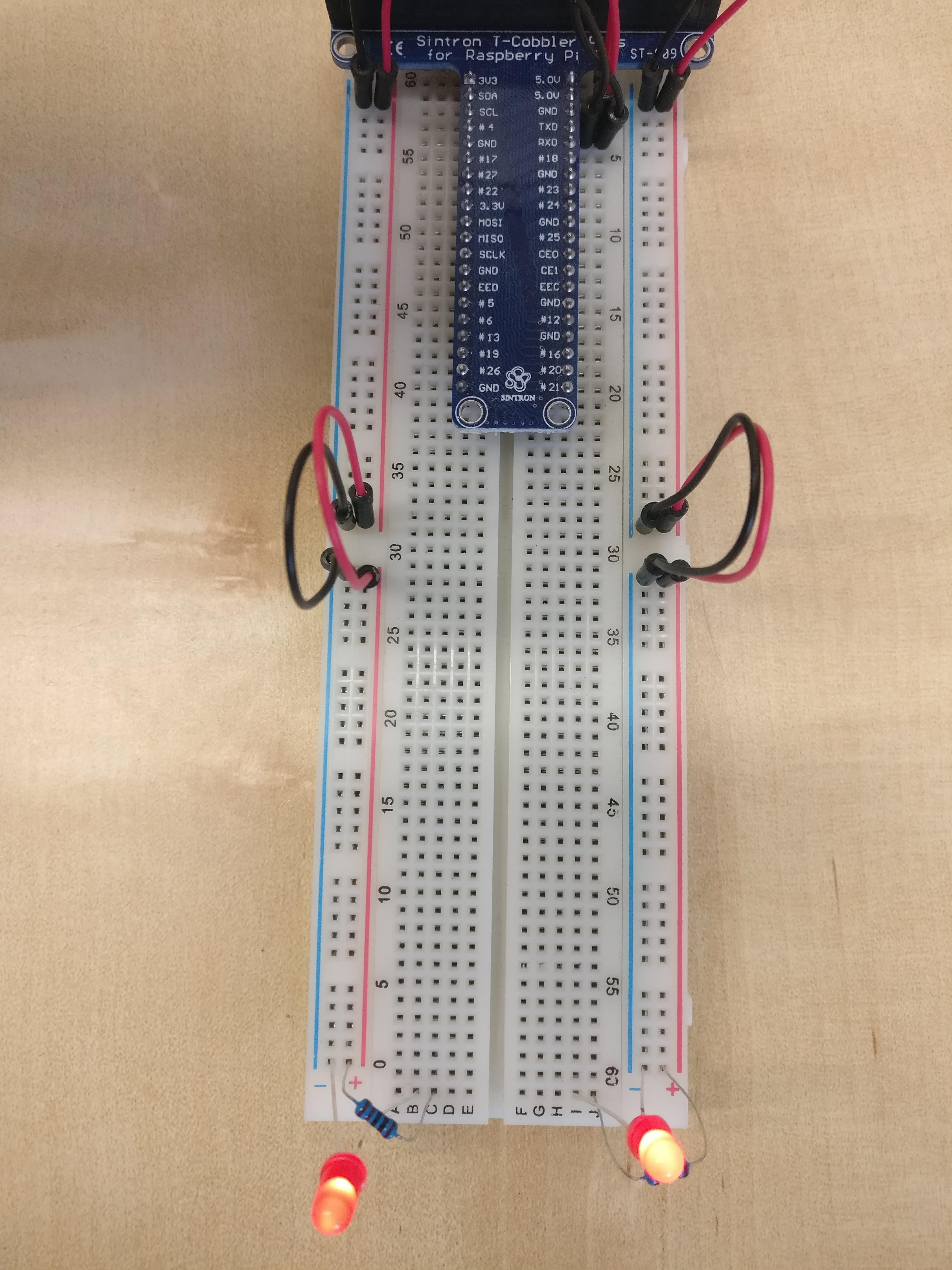
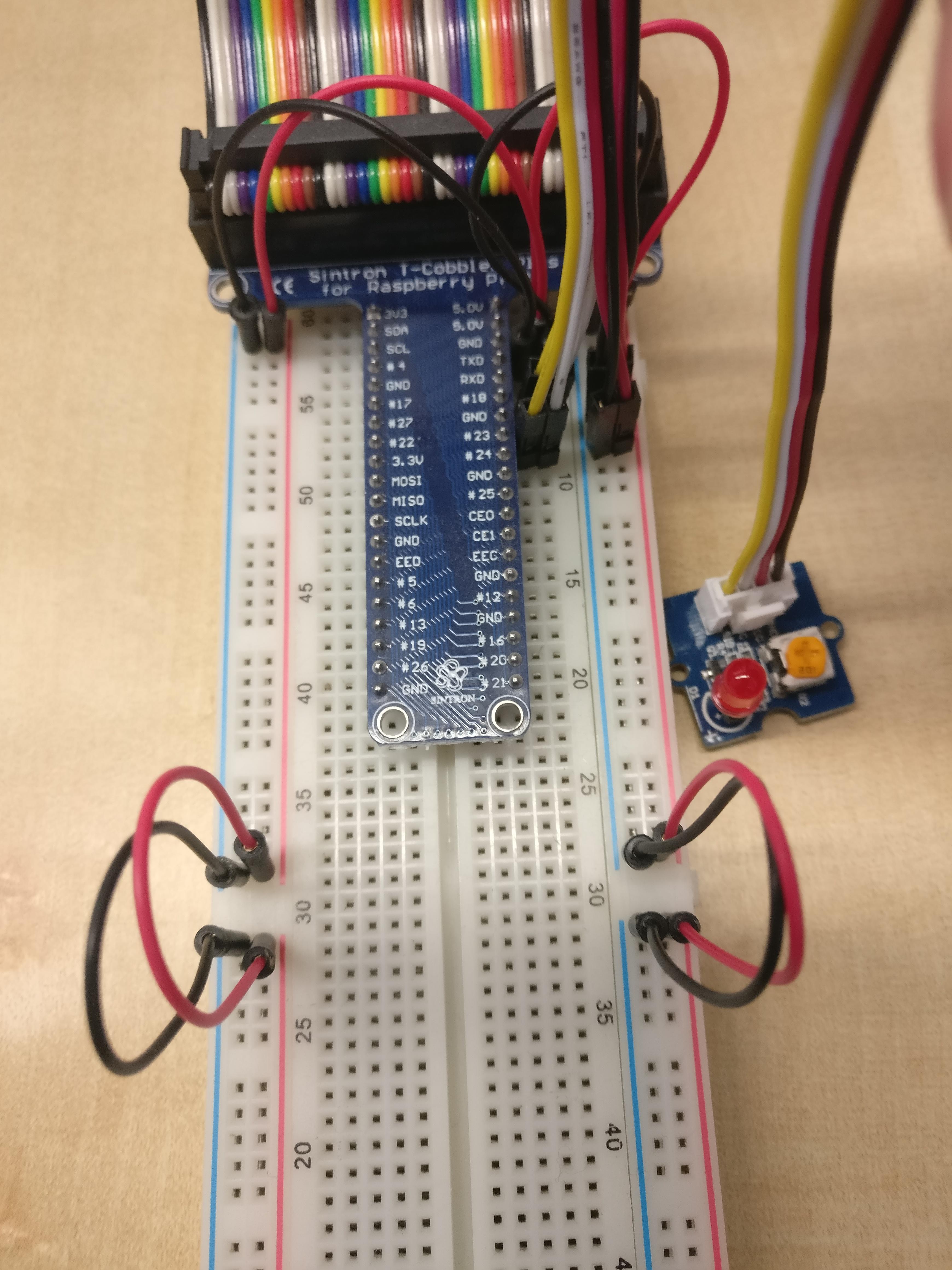
Connect the second half of the breadboard with current. If you like you can put LEDs at the end.
-
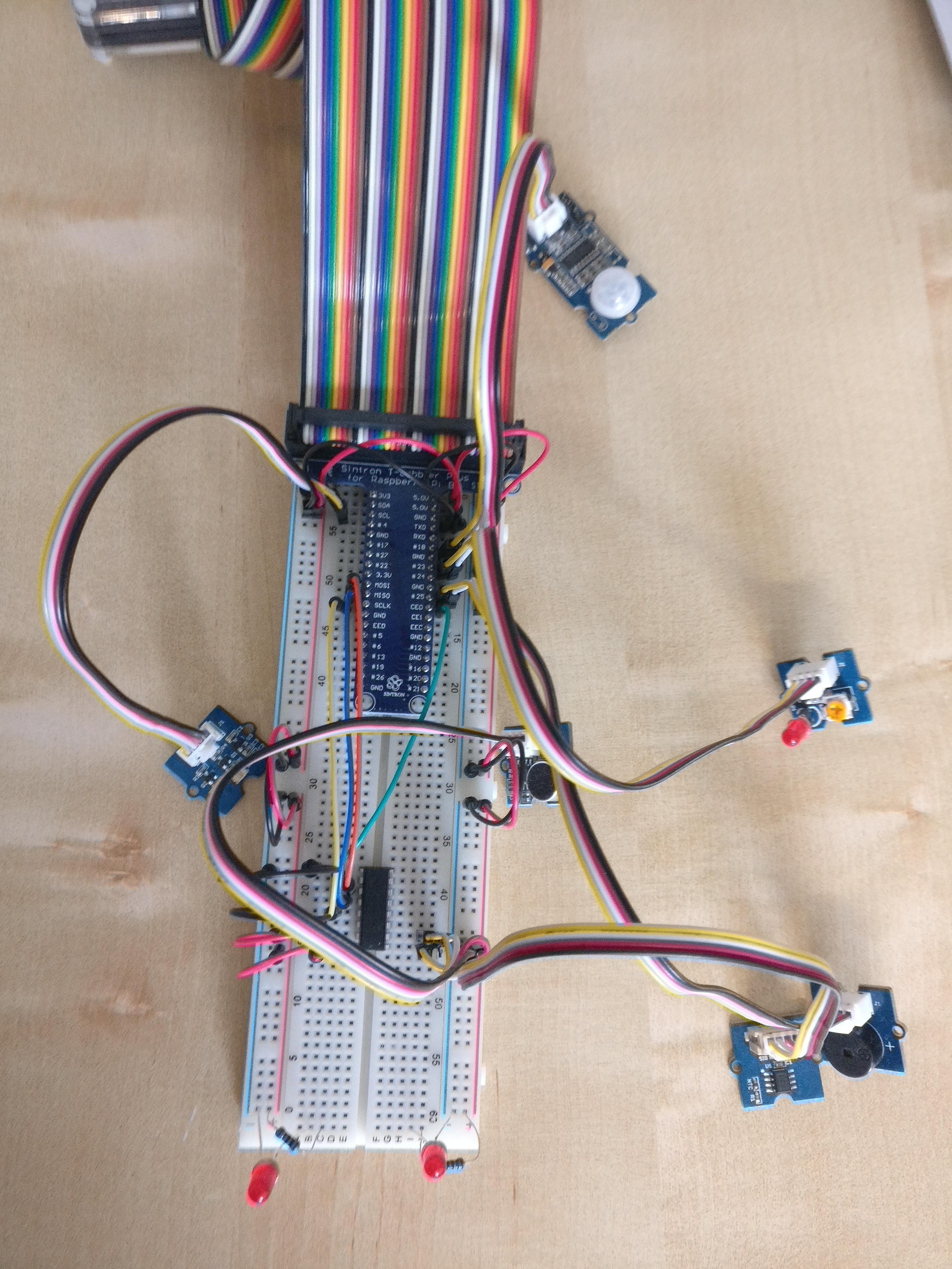
Connect the PIR Motion Sensor wiht a digital pin (We use pin #18, but you can use any pin which is labeled with a number. Keep in mind to change the configuration accordingly). Connect the yellow pin from the sensor into the Breadboard next to the Pin #18 from the T-Coppler and connect the black pin with ground and the red pin with voltage. The white pin does not carry any signal, so we can connect it next to the yellow pin or just leave it away.
-
Connect the LED wit a digital pin accordingly (Pin #23).
-
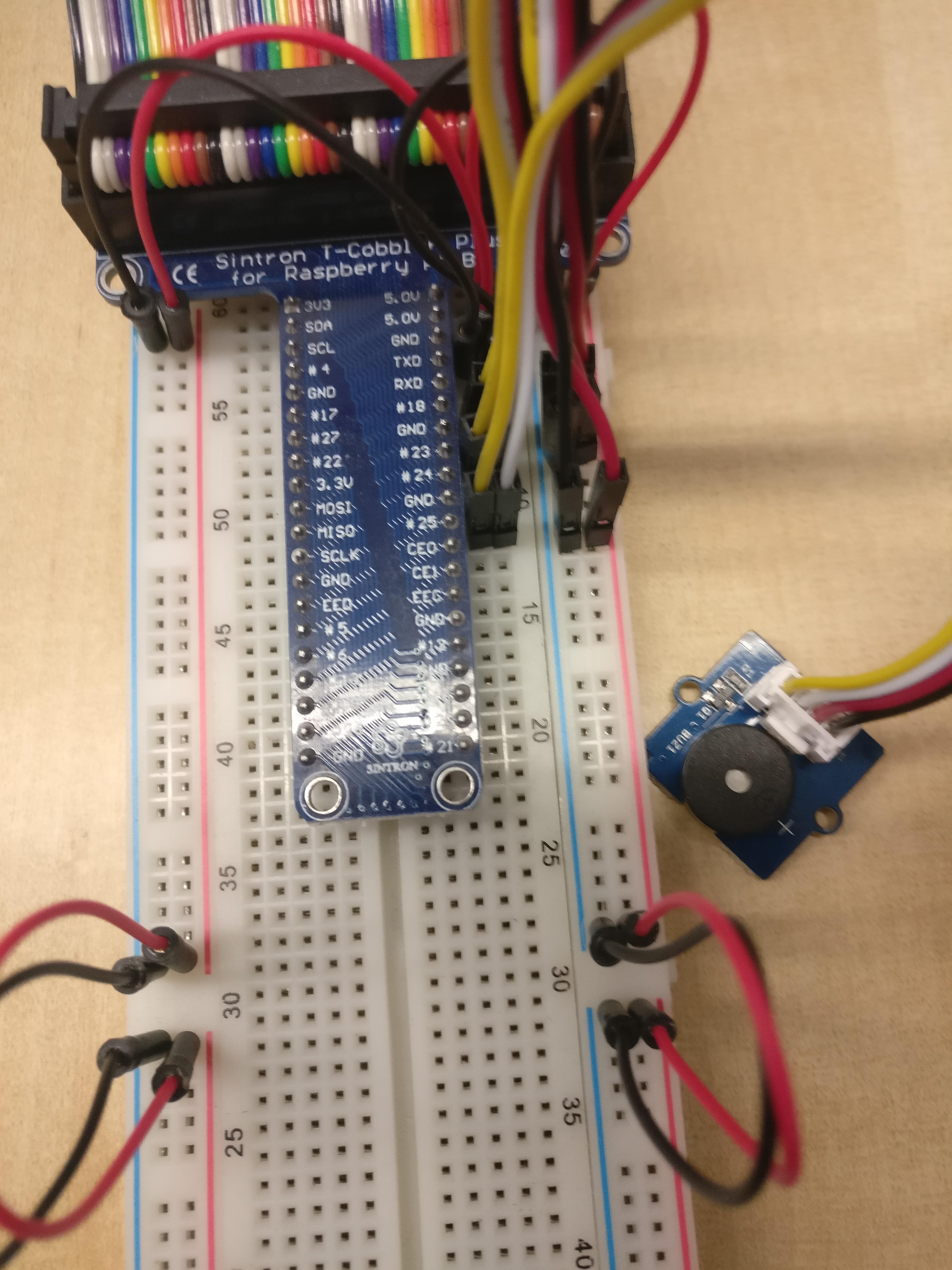
Connect the Buzzer wit a digital pin accordingly (Pin #25).
-
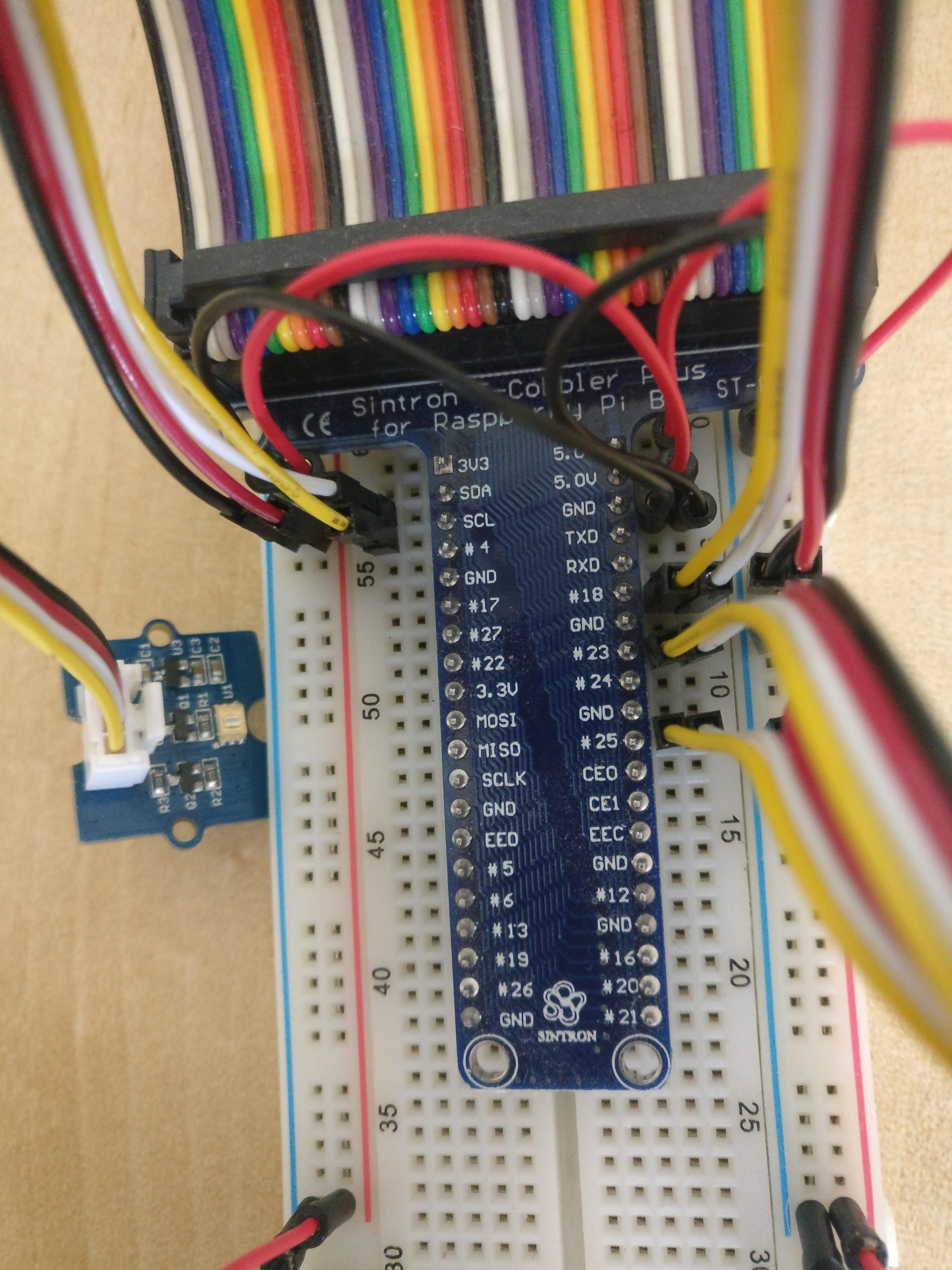
Connect the Digital Light Sensor with the I2C Bus. On the backside of the Digtal Light Sensor you see both I2C wires SDA (white) and SCL (yellow). Connect them on the Breadboard next to the Pin SDA and SCL from the T-Coppler then connect the current.
-
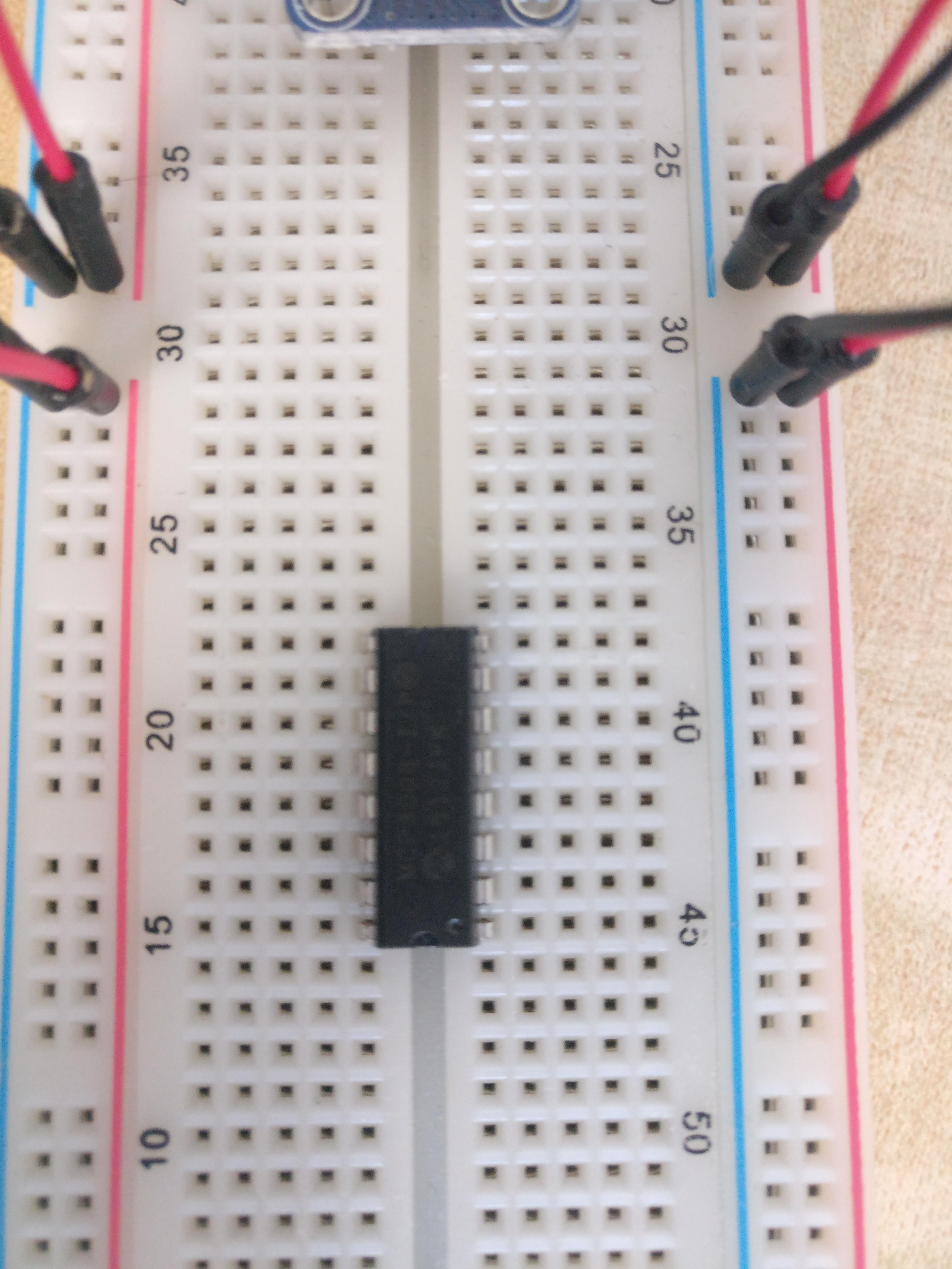
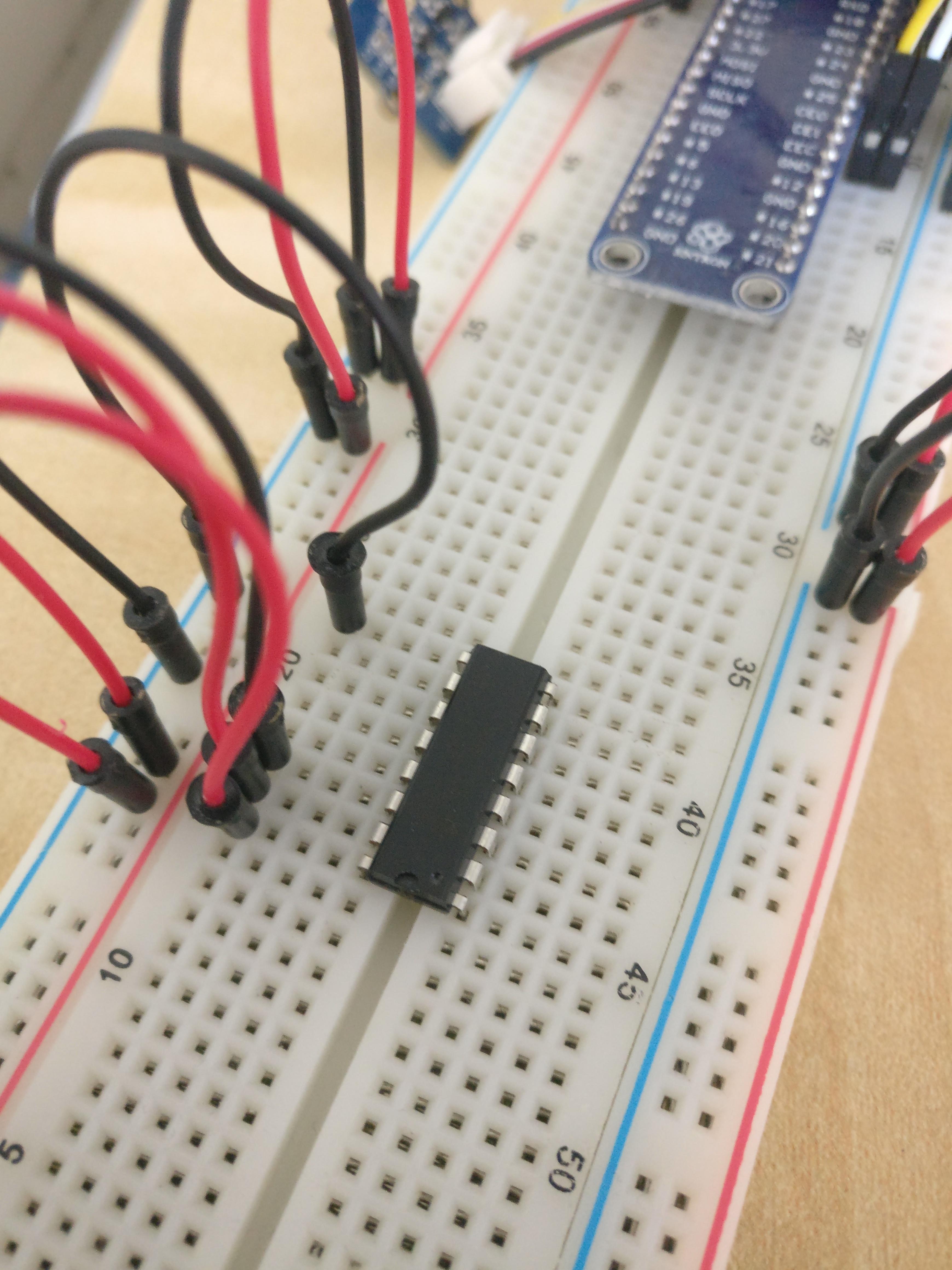
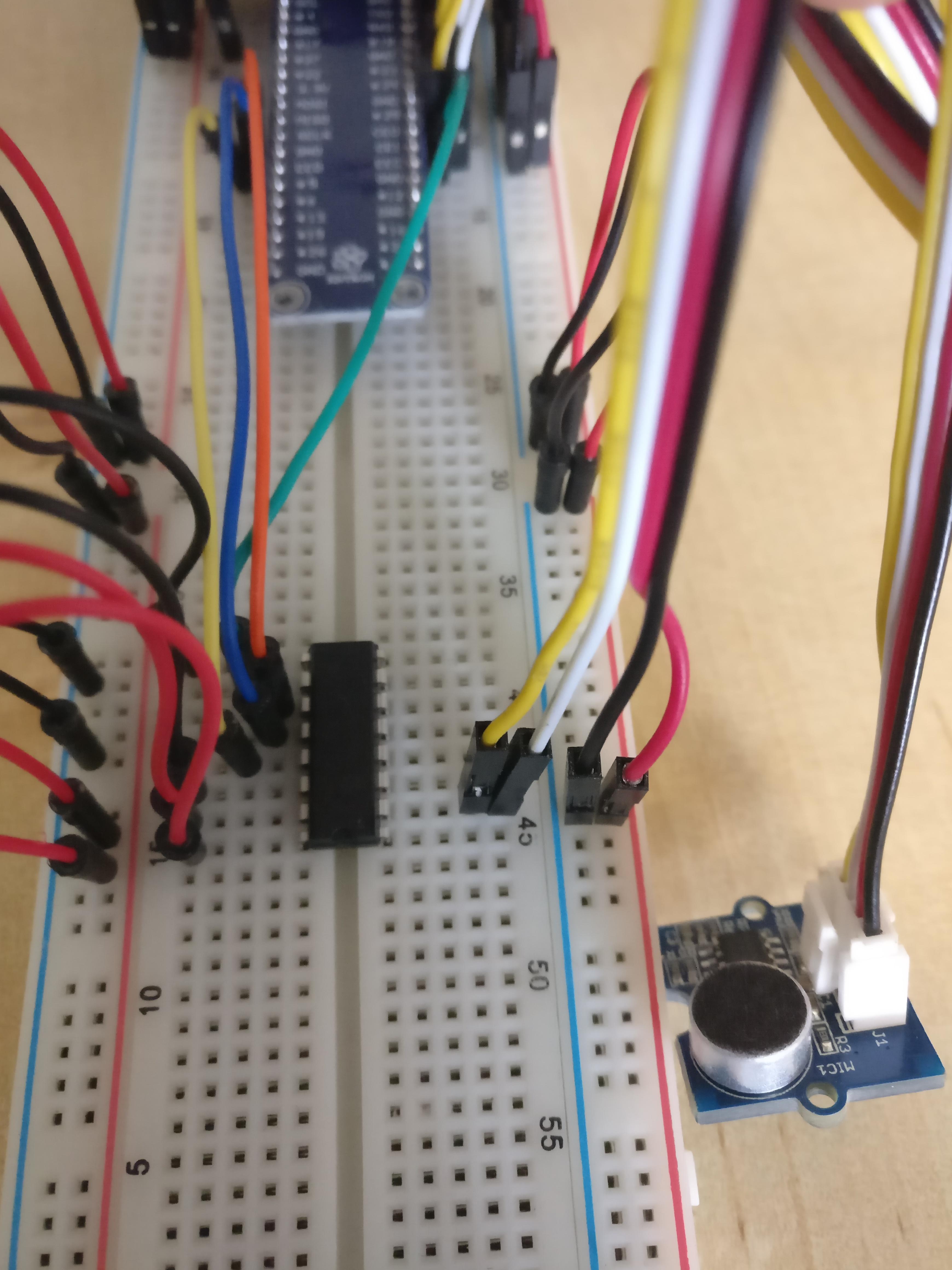
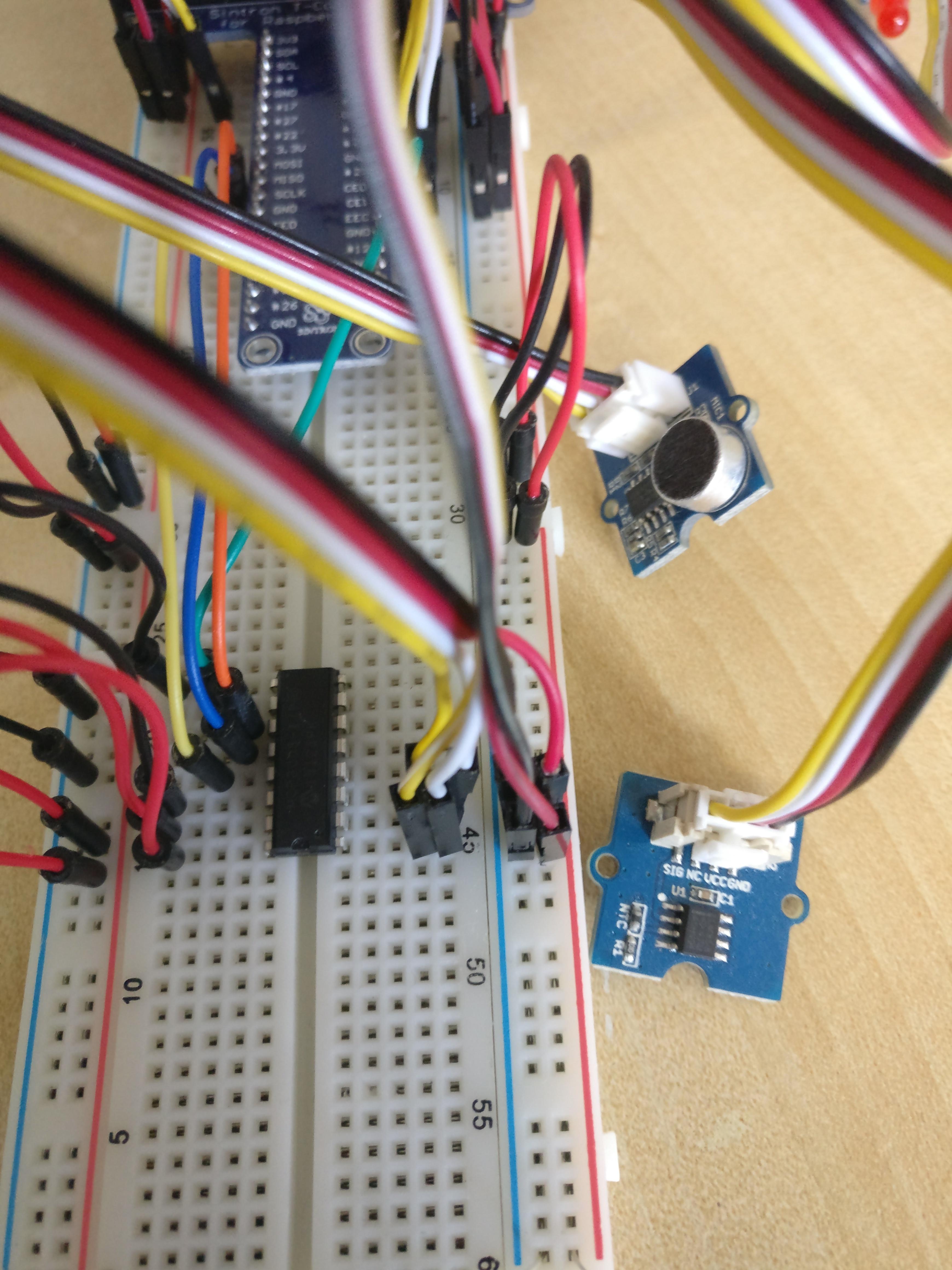
Put the MCP 3008 in the middle of the Breadboard with the nose down. Here you can find the datasheet of the MCP 3008 for reference.
-
According to the datasheet we now connect voltage and ground with the ADC.
-
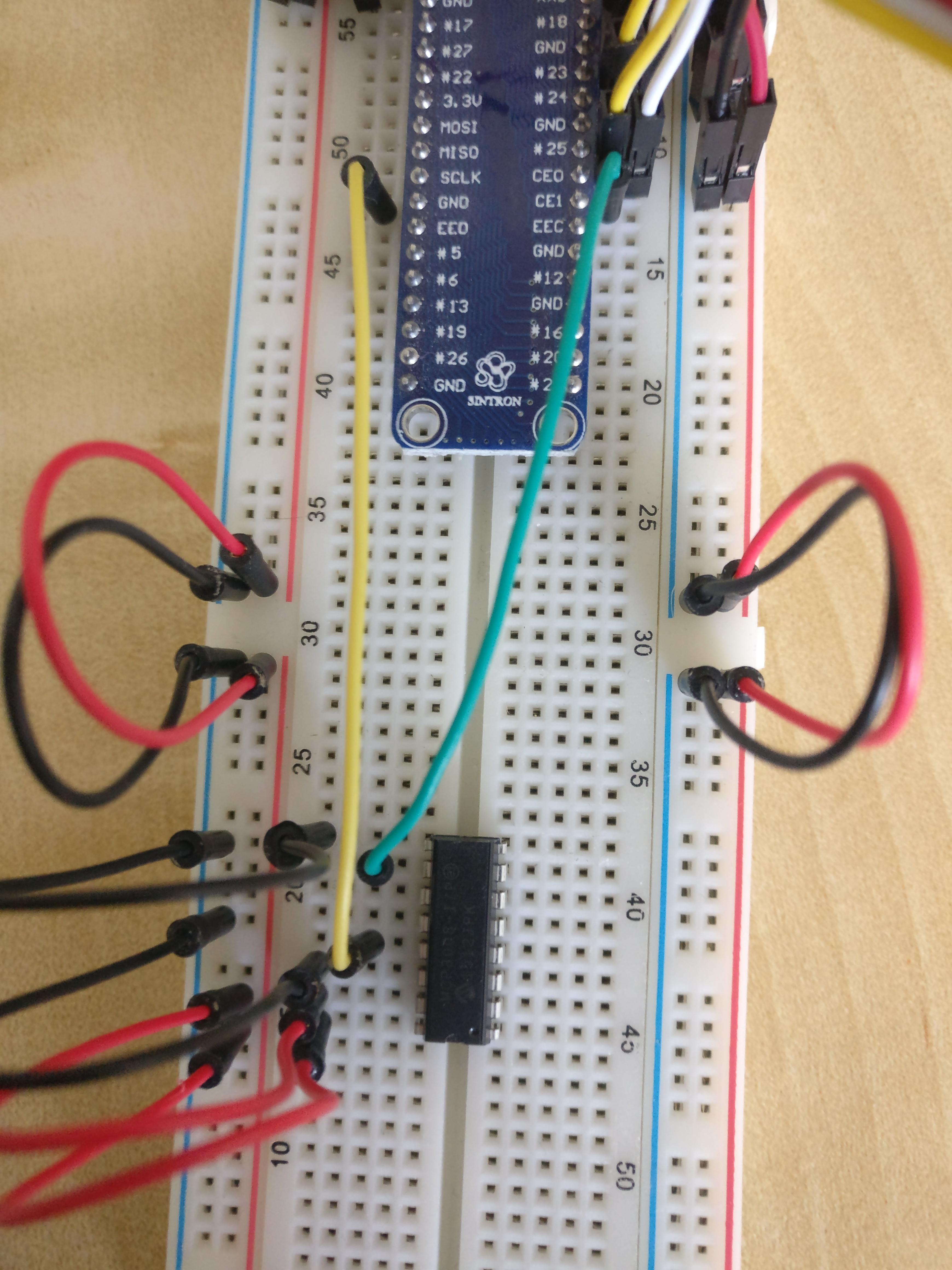
Now we have to connect the ADC to the SPI Bus of the Raspberry Pi. Therefore we need data in (DIN) and out (DOUT), chipselect (CS) and a clock (CLK).
-
At first we connect the clock with the pin SCLK and the chipselect with CE0 on the Breadboard next to the T-Coppler.
-
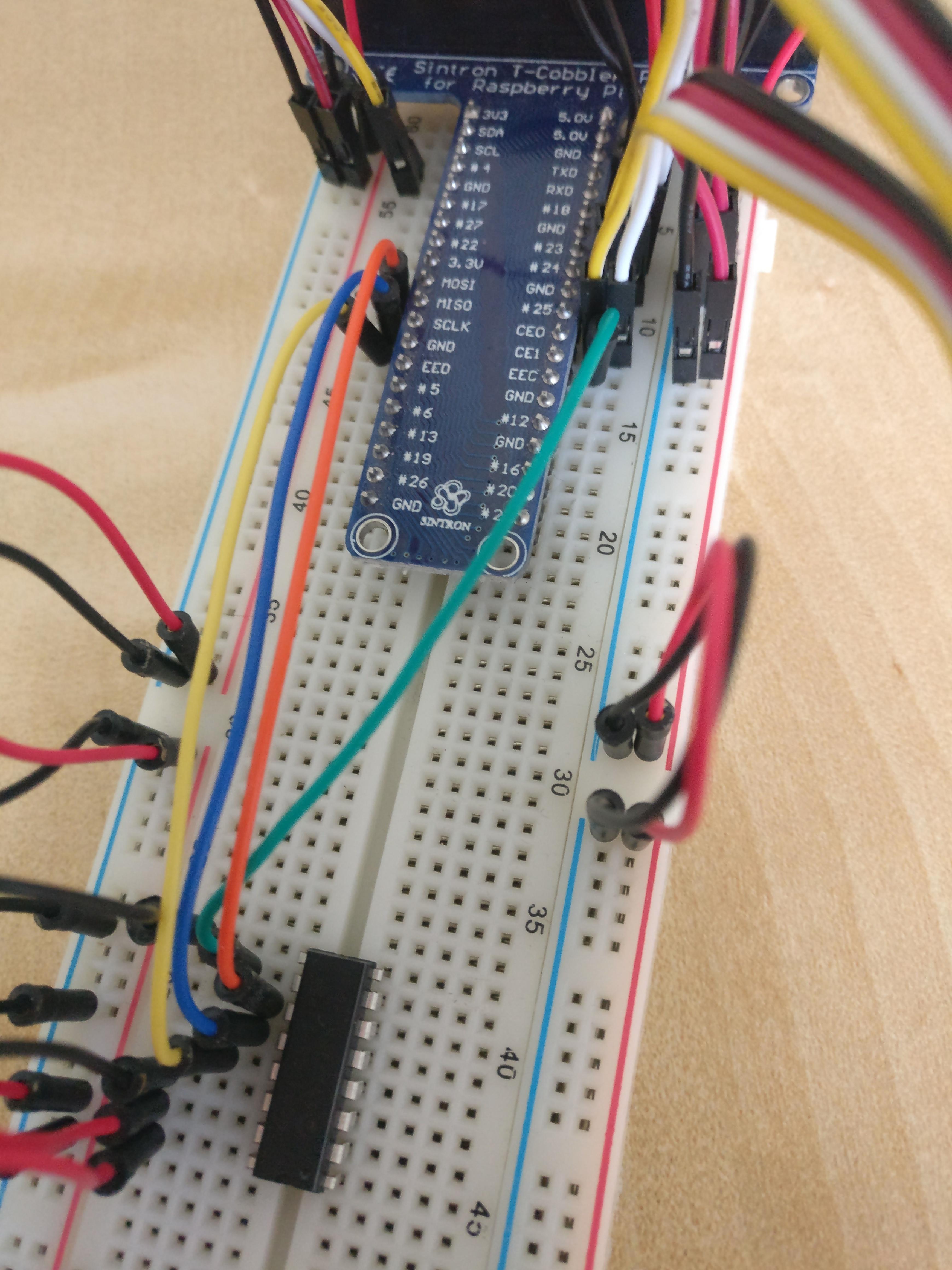
Now we connect both data lines. Therefore we connect DOUT with MISO and DIN with MOSI.
-
We now can connect the analog sensors. The channels are on the right side of the ADC, just remember to change the configuration accordingly. We connect the Analog Sound Sensor to the channel 1 of the MCP 3008.
-
On Channel 0 we connect the Analog Temperature Sensor.
-
Now the wiring is done. You could always connect more sensors at a later time. The digital sensors or actuators are connected directly with a digital pin. I2C sensors are just connected the way the Digital Light Sensor is connected. And analog sensors are just conencted to the MCP 3008 on any othe channel (complete right side of the ADC).